Stalagmite®
Articulated Triple Tray (Quad)... ~1~
ATT: Quadrant Articulated Triple Tray System (stand-alone)
The standard Stalagmite® Pouring Jig is not needed with this design as it already has its own Pin-Locator pointer system built in.
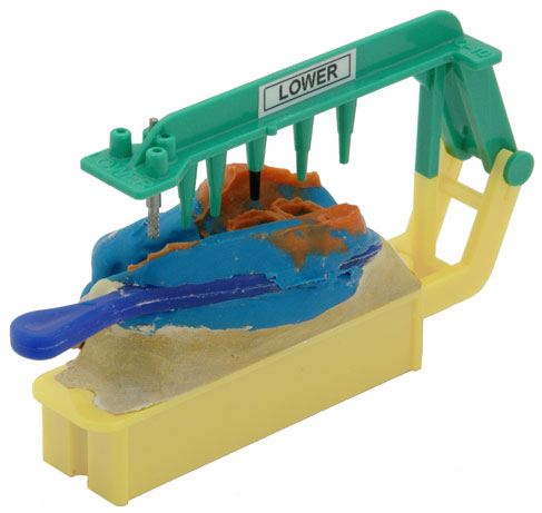
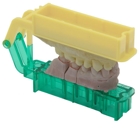
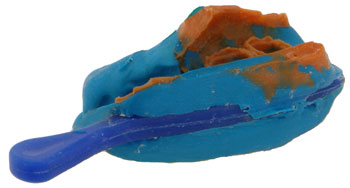
Left image shows that Triple Tray impression's opposing side has been poured. Notice that the impression was positioned with the Medium Lower Pin-Locator. Position the impression
so that the pointers are between 2 and 3mm from the margins and as close as possible to
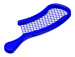
the center of each tooth location (this will insure that the die model doesn't end up too thick). Right image shows that the Lower Pin-Locator has been replaced with a Medium Lower Base and the die side of impression has been poured and trimmed.
Note: If you select the correct Pin-Locator when pouring the opposing side of impression; it will be impossible to select and use the wrong Die Pin Base because of the Male-Female Hinge design. In the above example: If you remove the Lower Pin-Locator and try to attach an Upper Die Pin Base, it will not work because the Upper Die Pin Base has a Female Snap Hinge.
Left images are the Upper and Lower Medium ATT Quadrant Pin-Locators. Right images are the Upper and Lower Medium ATT Quadrant Bases.
Notice, that all Upper parts have Female Hinges and all Lower parts have Male hinges.
The Upper and Lower ATT Quadrant Oppossing Bases. These two opposing bases work with all three sizes.
It is very easy to remove the opposing model from the Opposing Base in case the bite relationship needs to be re-established. There is a pilot hole under each of the six retention pins in the Opposing_Base. Insert a 3/32" or 2.38mm drill into a hand-piece and drill into the pilot hole at least 2 mm. This will sever the retention pins and allow the stone model to be removed from the Opposing_Base.
ATT Quadrant parts depicting the unique features of the the Medium Upper Die Pin Base and the Lower Opposing Base.
The die pin holes are precision tapered to receive our removable Tapered Die Pin. The index pins prevent the die from rotating or twisting and are strategically located to prevent putting a die into the wrong location. (However, this does not prevent you from putting a die into the same location on the wrong base.) If this happens; it's easy to see that the saw cut sides of the die do not match up with the saw cut lines in the plastic base.
The notches at both ends of the Bases will receive a plastic stop rod (3/16" or 4.75mm). A thin membrane must first be removed at the end of each notch.
Opposing Base retention pins can be drilled out from the bottom so the opposing model can be removed and relocated. This is handy when a bite relationship needs to be corrected and is the safest method to use.
Caution: If using a small tourch to heat up the hinge to re-establish the bite relationship, be very carefull not to get to close to the snap area, as this will adversely affect its grip. Heating up the Male hinge is the safest. Slowly heat up the hinge arm uniformly by teasing the heat on all sides. It will start to bubble if you get it too hot.